
Page 213 - HUNGER Dichtungen
P. 213
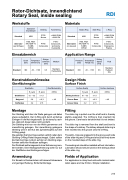
Rotor-Dichtsatz, innendichtend Rotary Seal, inside sealing
RDI
< Ø400 POM > Ø400 PA
 Werkstoffe
Standard NBR
Einsatzbereich
PTFE- Bronze
< Ø400 POM > Ø400 PA
Materials
Standard NBR
PTFE- Bronze
   elastischer Grundkörper
  Gleitring
  Kammerring
    Elastic Ring
  Slide Ring
  L-Ring
     Alternativ
(auf Anfrage)
  FKM, FKM- HW, NBR-TT, H-NBR, EPDM
  PTFE- Compounds
   PTFE- Compounds, technische Kunststoffe
   Alternative
(on request)
  FKM, FKM- HW, NBR-TT, H-NBR, EPDM
  PTFE- Compounds
   PTFE- Compounds, Engineering Plastics
 Application Range
   Pressure [bar]
  Temperature Range [°C]
  Sliding Speed [m/s]
  Fluid
  Standard
   360
 -30 ... +100
   0,5
  Standard- Hydraulic Oils
    Druck [bar]
  Temperatur- bereich [°C]
  Gleitge- schw.keit [m/s]
  Medium
  Standard
   360
 -30 ... +100
   0,5
  Standard- Hydrauliköle
   Konstruktionshinweise Oberflächengüte
Ra [μm]
0,1 - 0,3
0,8
3,2
Design Hints Surface Finish
 Rauhtiefen
  Oberflächenhärte
  Surface Quality
  Surface Hardness
     Gleitflächen
Nutgrund
Nutflanken
Montage
Rt [μm]
≤ 1,5
≤ 6,3
≤ 15
[HRC]
> 40
Sliding Surfaces
Groove Base
Groove Sides
Fitting
Ra [μm]
0.1 - 0.3
0.8
3.2
Rt [μm]
≤ 1.5
≤ 6.3
≤ 15
[HRC]
> 40
        Der Gleitring wird über die Welle gezogen und dabei etwas aufgedehnt. Der O-Ring wird durch einfaches Einlegen in die Nut eingebracht. Es ist darauf zu ach- ten, daß sich dieser dabei nicht verdreht.
Der Gleitring wird nun von der Welle genommen und nierenförmig gebogen. Der nierenförmig gebogene Gleitring wird in die Nut des Zylinderkopfes auf den O-Ring gelegt.
Die geteilten Kammerringe werden seitlich neben dem Gleitring-O-Ring-Paket eingeschnappt. Dabei sollten die Kammerringe rundum auf den am Gleitring ange- formten seitlichen Absätzen aufliegen.
Der Dichtsatz sollte insgesamt ohne Schmierung mon- tiert werden. Eine Montageschmierung sollte nur auf der Gleitfläche des Gleitringes erfolgen.
Anwendung
Für Einsatz in Drehverteilern mit kleinem Einbauraum und geringer Reibung. Einfache Montage.
The slide ring is pulled over the shaft and is thereby slightly expanded. The O-Ring is then inserted into the groove. Care has to be taken that it is not twisted.
The slide ring is removed from the shaft and bent to the shape of a kidney. The kidney-shaped slide ring is then inserted into the groove onto the O-Ring.
The split L-rings are snapped into the groove each side of the slide-ring and O-Ring and should sit firmly down on the moulded steps of the slide ring.
The sealing set should be installed without lubrication. Lubrication should only be used on the sliding surface of the slide ring.
Fields of Application
For application in rotary feed units with minimal instal- lation space and low friction. Simple installation.
213
